-
Phone
+8629891****
-
Address
The 30th Floors,Kaixuan Massion,Xuanwu Road West,Weiyang District
-
E-mail


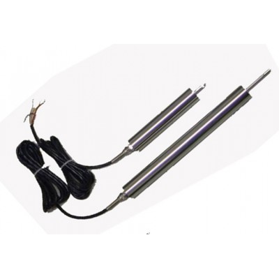
Straight Line Displacement Sensor
Straight Line Displacement Sensor,Electrical Equipment & Supplies
Description
Model: WYDC LVDT
Description:
The WYDC LVDT differential transformer displacement sensor has good environmental adaptability. It is widely used to measure various physical quantities that can be changed into displacement in advance and to measure the mechanical quantities (such as tension, pressure, vibration, liquid level, etc.) that can be converted into displacement. Microelectronic technology is adopted in the amplifying circuit of the sensor
The Working Principle
The WYDC LVDT differential transformer is a sensor that converts the linear displacement into a simulated voltage. Because of its structure as a whole, the durability and environment resistance are excellent, and the temperature range is -20℃-120 Differential Transformer displacment sensot is made of a promary coil, a sesncendary coil and a movable core. Added fixed voltage and frequency of sine wave excitation on primary coil and secondary coil induces response voltage by moveable core.The output characteristics of two of the secondary coil and the excitation signal is a differential output with the frequency of the AC voltage. Through the detection circuit to be output DC voltage displacement. The detection circuit consists of a rectifier diode and a RC filter. The measurement range is a moving travel of a movable iron core, which is usually from a number of +mm to hundreds of mm. When the moving iron core is in the center position, the output voltage is 0 V: the positive and negative voltage, which is proportional to the moving distance, is produced when the movement is left and right. The linearity is less than 1% and the detection precision is m. The error increases when it exceeds the prescribed travel.
Features:
No active contact, high reliability and long life;
The resolution is high and the sensitivity is good.
High linearity and good repeatability.
Wide range of measurement (low resolution when measuring range is wide)
External Size and Technical Parameter
|
Spec |
Measure Range(mm) |
A(mm) |
L(mm) |
△L(mm) |
D(mm) |
E(mm) |
||
|
MIN |
MAX |
|||||||
|
5L、2.5D |
5、±2.5 |
180 |
30 |
54 |
15 |
Φ26 |
M5 |
|
|
10L、5D |
10、±5 |
180 |
30 |
80 |
15 |
Φ26 |
M5 |
|
|
20L、10D |
20、±10 |
180 |
30 |
95 |
15 |
Φ26 |
M5 |
|
|
30L、15D |
30、±15 |
180 |
30 |
111 |
15 |
Φ26 |
M5 |
|
|
50L、25D |
50、±25 |
230 |
30 |
155 |
15 |
Φ26 |
M5 |
|
|
100L、50D |
100、±50 |
280 |
30 |
205 |
15 |
Φ26 |
M5 |
|
|
150L、75D |
150、±75 |
380 |
30 |
265 |
15 |
Φ26 |
M5 |
|
|
200L、100D |
200、±100 |
400 |
30 |
321 |
15 |
Φ26 |
M5 |
|
|
300L、150D |
300、±150 |
540 |
30 |
485 |
15 |
Φ26 |
M5 |
|
|
400L、200D |
400、±200 |
670 |
30 |
644 |
15 |
Φ26 |
M5 |
|
|
500L、250D |
500、±250 |
830 |
50 |
749 |
15 |
Φ26 |
M5 |
|
|
Comprehensive Accuracy |
0.25%、0.5%、1%F·S |
|||||||
|
Output Signals |
4~20mA、0~5 or 0~±5V、0~±10V |
|||||||
|
Power Voltage |
12V、15V、24VDC(standard) |
|||||||
|
Working temperature |
-10~60℃ |
|||||||
|
Zero Shift |
0.01%/℃ |
|||||||
|
Sensitivity Drift |
0.05%/℃ |
|||||||
|
Dynamic Frequency |
0~200Hz |
|||||||
Note: * L means unidirectional, D means bidirectional. *
Structure Diagram
Electric Connection:
Transmitter connecting the outsude by cable or connection box;
|
Wire color |
Terminal |
Connection |
|
Red |
1 |
V+ |
|
Yellow |
2 |
V-/GND |
|
Blue |
3 |
OUT+ |
a). Electric connection for transmitter with 3 -wire 4~20mADC output:
Reminders when choose models
|
Code |
Explanation |
||||||||||||||
|
Model |
WYDC/LVDT |
Straight Line Displacement Sensors |
|||||||||||||
|
|
Linear Travel |
X |
Unit: MM For example: 50MM,100MM |
||||||||||||
|
|
One way |
L |
Zero at one side, For example: 10L means 0-10MM |
||||||||||||
|
|
Two way |
D |
Zero at center, For example:10D means ±10MM |
||||||||||||
|
|
Accuracy |
1 |
0.5% |
||||||||||||
|
|
2 |
0.3% |
|||||||||||||
|
|
3 |
0.25% |
|||||||||||||
|
|
4 |
1% |
|||||||||||||
|
|
Output |
I |
4-20mA |
||||||||||||
|
|
V1 |
0-5V |
|||||||||||||
|
|
V2 |
0-10V |
|||||||||||||
|
|
V3 |
±5V |
|||||||||||||
|
|
V4 |
±10V |
|||||||||||||
|
|
Connection |
3 |
3 wire:power+ power- output |
||||||||||||
|
|
4 |
4 wire:power+ power- output+ output- |
|||||||||||||
|
|
Power supply |
G1 |
24VDC |
||||||||||||
|
|
G2 |
12VDC |
|||||||||||||
|
|
Shell Diameter |
K1 |
Φ26MM |
||||||||||||
|
|
K2 |
Φ20MM |
|||||||||||||
|
|
Zero |
A |
Zero at outside:meauring bar is outside,output 4mA or 0V |
||||||||||||
|
|
B |
Zero at inside: meauring bar is outside,output 20mA or 5V |
|||||||||||||
|
|
Measuring bar form |
1 |
Free slid |
||||||||||||
|
|
2 |
Spring back |
|||||||||||||
|
|
Probe |
1 |
M5 thread |
||||||||||||
|
|
2 |
Ball contact tip |
|||||||||||||
|
|
Shell form |
Y |
All-in-one |
||||||||||||
|
|
|
F |
Split |
||||||||||||
|
|
N |
Np specific |
|||||||||||||
|
|
T |
Specific |
|||||||||||||
|
|
Cable length |
X |
Unit:M standard:2M |
||||||||||||
|
|
|
||||||||||||||
